

INTRODUCTION
Torrent Guasp’s theory of cardiac function is based on the grouping of muscle fibers constituting the continuous myocardium, which folds to form the helical heart and thus shape the ventricular chambers. (1) Anterior and inferior to the right trigone (RT) lies the cardiac fulcrum (CF), a structure with osseous, chondroid, or tendinous histology depending on the specimen analyzed. This is the site where the fibers of the right segment (RS) and the ascending segment (AS), the juxtaposed origin and end of the continuous helical myocardium, attach.
The myocardium relies on the CF to generate ventricular torsion and detorsion. This structure in the human heart, its anatomy and function, was first described by Trainini et al. in 2019. (2,3)
OBJECTIVE
We conducted this study with the aim of correlating by echocardiography the trigones and the CF with topographic anatomy to understand the anatomofunctional characteristics of cardiac mechanics.
METHODS
We used a conventional scale, dissection kit, LED lamp, surgical loupes, a professional camera, and a Mindray M7 ultrasound machine. Thirty bovine hearts were dissected to standardize the dissection technique required to reach the CF. The anatomical location of the structures was compared between human and bovine species. The CF in humans and cattle has been extensively studied in previous studies and shows 100% concordance in location between the two species. (2,3) The difference lies in the fact that the CF in the bovine heart is macroscopically visible.
The fresh hearts were dissected, and the location of the trigones and the CF was identified. All adipose tissue adhering to the sulci was removed. An incision was made in the right and left atrioventricular grooves to enucleate both atria. The tricuspid septal leaflet (TSL), the right coronary (RCL) and noncoronary (nCL) leaflets of the aortic valve, and the basal interventricular septum (IVS) were identified. Subsequently, the TSL was resected in the apicalbasal direction and pulled toward the right ventricular (RV) chamber so that the CF was exposed underneath. Color coding of the trigones and the CF was performed using photo editing software. The colorcoded bovine hearts were sectioned to replicate the conventional section planes and axes used in conventional echocardiography, and all findings were correlated with echocardiographic projections from studies in our database.
Ultrasound Settings
Using a Mindray M7 ultrasound machine and a 2.5 MHz transducer, twodimensional long and short parasternal views, apical views, and subxiphoid views were obtained. Highquality images that allowed us to evaluate the heart’s fibrous skeleton were acquired. When configuring the equipment, it is important to consider the following aspects: 1) gain should be adjusted to optimize the signaltonoise ratio and avoid signal saturation; 2) depth should be adjusted to visualize the structure of interest; 3) the transducer frequency should be selected according to the depth of the area of interest being studied.
RESULTS
Dissection and topographic anatomy of the cardiac fulcrum
The CF is located in the IVS below the aortic root, in relation to the left and right aortic leaflets, behind the TSL, and in front of the pulmonary artery (PA).
When enucleating the right atrium (RA) and preserving the interatrial septum (IAS), the CF is located by palpating the IAS above the insertion site of the TSL, in a whitish, protruding region with a hard, stony consistency in the bovine specimen (Figures 1 and 2). By dissecting the TSL from its ventricular surface and pulling it toward the ventricular chamber, the CF is exposed. (3)
Fig. 1
Anatomical location of the cardiac fulcrum (CF). A: Whole bovine heart, viewed from the base. With the atria removed, the two ventricles, great vessels, and atrial surface of the tricuspid valve leaflets are exposed. B: Bovine heart with the right atrium removed, showing the TSL. Above its insertion, the CF is located in a region characterized by a distinct protuberance of hard, stony consistency (white arrows). C and D: bovine heart: structures related to the CF. Note the insertion of the TSL below the CF and the RCL (C) and nCL (A) above it. In D, the TSL has been resected and pulled toward the RV chamber (TV and black arrows), exposing the CF (large black arrow). The IAS has also been resected and displaced (green arrows). E: bovine heart. The atria and the free wall of the RV have been enucleated to expose the CF. The CF is located in close proximity with the insertion base of the TSL and below the aortic hemi annulus relative to the RCL and nCL of the aortic valve. The left main coronary artery (LMCA) is positioned at 180° from the cardiac fulcrum. F. CF viewed from the RV. G: Apical and basal loops. H: Resected bovine osseous CF. Note the helical imprint of the structure.
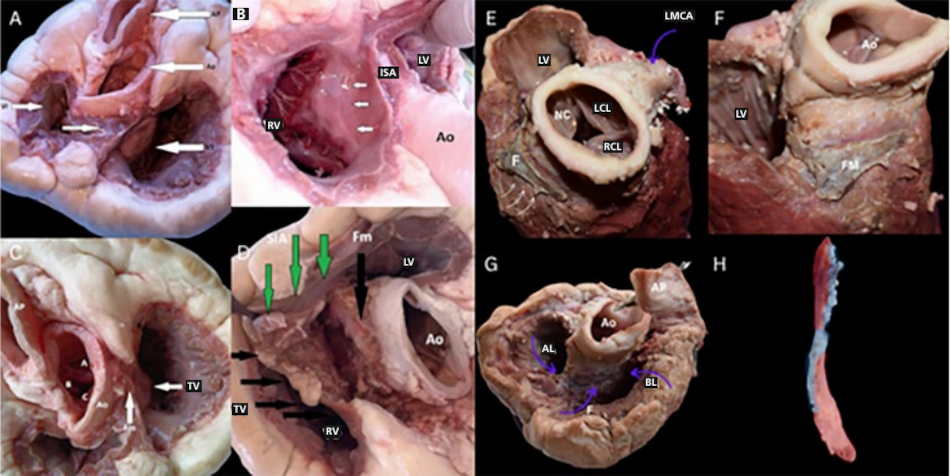
Ao: aorta; AL: apical loop; BL: basal loop; F and Fm: fulcrum; ISA: interatrial septum; LCL: left coronary leaflet of the aortic valve; LMCA: left main coronary artery; LV: left ventricle; nCL: noncoronary leaflet of the aortic valve; PA: pulmonary artery; RA: right atrium; RCL: right coronary leaflet of the aortic valve; RV: right ventricle; TSL: tricuspid septal leaflet. Authors’ own images.
Fig. 2
Bovine heart. Color coding of the trigones, coronary filaments, and cardiac fulcrum.
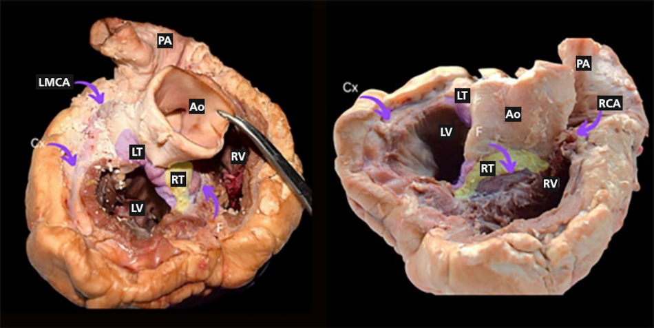
Ao: Aorta; Cx: Circumflex artery; F: Fulcrum; LT: Left trigone; LMCA: Left main coronary artery; LV: Left ventricle; PA: Pulmonary artery; RCA: Right coronary artery; RT: Right trigone (yellow); RV: Right ventricle. Authors’ own images.
Echocardiographic Correlates
We identified the CF, the trigones, the segments of the continuous helical myocardium, and the related anatomical structures. The findings were compared with echocardiographic projections obtained from healthy patients. (Figure 3) (4,5)
Fig. 3
Bovine heart. Left: section at the level of the short axes in parasternal views. SA: conventional short axis; SAGV: short axis of the great vessels. Right: section level of the apical views.
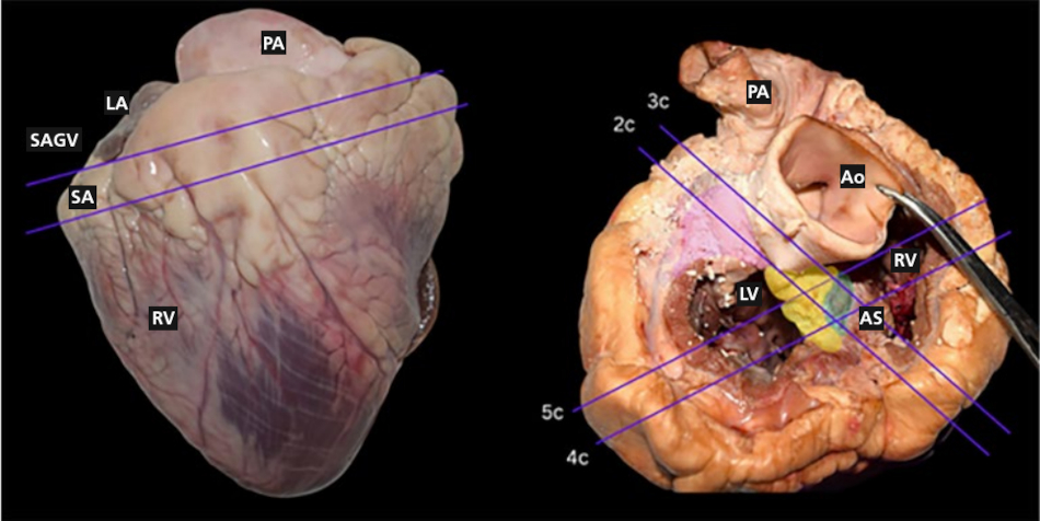
2c: two chambers, 3c: three chambers, 4c: four chambers, 5c: five chambers. Green: cardiac fulcrum. Ao: aorta; Ap: pulmonary artery; AS: ascending segment; LA: left atrium; LV: left ventricle; RV: right ventricle. Lilaccolored region: left trigone; yellowcolored region: right trigone. Authors own images.
Echocardiographic views
Parasternal views
Long axis view. The free wall of the right ventricle (RV) is visible, consisting of the right segment of the basal loop (BL); below it, the interventricular septum (IVS) is formed by the two segments of the apical loop (AL). At the ventricular base, the four segments of the helical myocardium are visible, while the descending (DS) and ascending (AS) segments are located in the medial and apical portions. The posterior papillary muscle marks the origin of the AS.
In the parasternal long axis view, the IVS is divided into two sectors by an echogenic line separating the AS and DS. It is an area of high friction with high hyaluronic acid content. (6) The AS inserts beneath the RCL and nCL into a hyperechoic structure: the CF is located below and anterior to the RT (Figure 4).
Modified long axis: a long axis of the RV is achieved as shown in Figure 4. Above the TSL, on the lower IAS, the tip of the AS is seen inserting into an echogenic structure: the RT and the CF.
Short axis over the great vessels: the base of the TSL continues within the IVS with a hyperechoic structure, the fibrous skeleton of the heart. The reflected echo generates an image that stands out from the surrounding tissue due to its striking brightness and blurred edges: the RT and the CF. In this view, it is important to identify the RCL and nCL as well as the base of the TSL. These structures are what mark the location of the CF with reasonable accuracy. (Figure 4).
Fig. 4
Parasternal views. A. Bovine heart and on the right its echocardiographic counterpart in humans. Parasternal long axis. B. Zoomed in with focus on the TSL. Blue arrows: AS entering the CF (RT). White arrow: TSL. Note the brightness of the structures that make up the heart’s fibrous skeleton. C. Bovine heart sectioned at the level of the great vessels and, on the right, its human echocardiographic counterpart: parasternal shortaxis view at the level of the great vessels’ outflow. Below the RCL and nCL and in close proximity to the TSL insertion site (red arrow) lies the CF (green circle). The origin of the TSL is located 180° relative to the CF (on the opposite side of the image). D. Shortaxis view at the level of the MV and TV. The base of the TSL (red arrow) continues with the CF (green circle) within the IVS (bright structure).
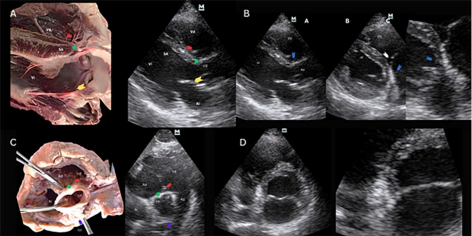
Ao: aorta; AS: ascending segment; CF: cardiac fulcrum; LA: left atrium; LMCA: left main coronary artery; LV: left ventricle; nCL: noncoronary leaflet; PA: pulmonary artery; RA: right atrium; RCL: right coronary leaflet; RT: right trigone; RV: right ventricle; TSL: tricuspid septal leaflet. Red arrow: TSL, yellow arrow: anterior leaflet of the mitral valve. Authors’ own images.
Basal short axis: On the shortaxis LV view between the great vessels and the mitral valve (MV), a bright area adjacent to the TSL is visible. This corresponds to the RT and the CF.
In this view, the RS forms the free wall of the RV; the AS corresponds to the right ventricular endocardium entering the CF, while the left segment (LS) correlates with the posterolateral region of the LV. (Figure 4).
Apical views
Four chambers: the atria and ventricles are visible. Additionally, the MV and TV. At the apex of the heart, adjacent to the insertion, the echogenic transition separating two media of different tissue density is documented: one of the media is the RT of the heart, and the CF is immersed beneath it. The AS enters the CF with muscular pigmentation. (Figures 5 and 6).
Fig. 5
Apical views. A. Sectioned bovine heart and on the right its human echocardiographic counterpart. Fourchamber view: at the cross, on the interatrialventricular septum is an image that stands out for its brightness, the fibrous skeleton of the heart. Within it lies a structure where the helical myocardium begins and ends: the CF. The AS enters the hyperechoic zone. B. Sectioned bovine heart and on the right its human echocardiographic counterpart. Fivechamber view: left atrium. The AS enters the CF through its inferior border. C. Sectioned bovine heart and on the right its human echocardiographic counterpart. Apical 2-chamber view: the AS from the apical loop enters the CF through its inferior border (green circles). The CF is shown in a longitudinal section. D. Sectioned bovine heart and on the right its human echocardiographic counterpart. Threechamber view: the AS enters the CF through its inferior margin (green circles). Red arrow: TSL, yellow arrow: anterior leaflet of the mitral valve. Anterior mitral valve (yellow arrow).
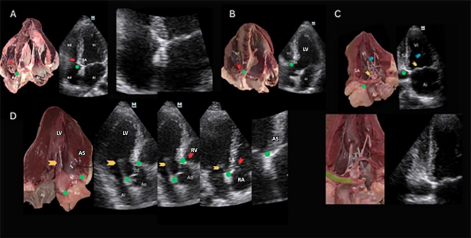
Ao: aorta; AS: ascending segment; CF: cardiac fulcrum; LA: left atrium; LMCA: left main coronary artery; LV: left ventricle; nC: noncoronary aortic valve leaflet; RA: right atrium; RT: right trigone; RV: right ventricle. TSL: tricuspid septal leaflet. Authors’ own images.
Fig. 6.
Apical fourchamber view. The AS is seen entering the RT and the CF at its lower margin (green arrow). The structures that stand out most clearly are the CF, RT, and right coronary filum. The latter surrounds the tricuspid annulus and is adjacent to the CS. Right: closeup view of the same structures.
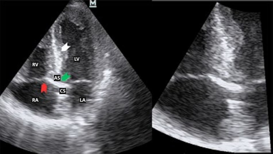
AS: ascending segment, CS: coronary sinusLA: left atrium, LV: left ventricle, RA: right atrium, RV: right ventricle. Green arrow: right trigone, right coronary filum, and cardiac fulcrum. White arrow: overlapping segments of the continuous helical myocardium (ascending and descending segments of the apical loop). Area with a large friction surface separated by high hyaluronic acid content. Authors’ own images.
Five chambers: atria, RV, LV, left ventricular outflow tract (LVOT), and aorta (Ao). Additionally, the MV and TV. Adjacent to the insertion base of the TSL, there is an echogenic transition: one of the media is the RT, and the CF is immersed beneath it. The other structure with lower tissue density are the terminal fibers of the AS. (Figure 5).
Two chambers: LA, LV, papillary muscle, part of the RT adjacent to the CF, the mitral and tricuspid valves. Below the CS, adjacent to the posterior mitral valve leaflet, an echogenic transition is documented that separates two media of different tissue density: one of the media is the RT, and below it is the CF. In this case, the ultrasound beam travels along the major axis of the structure, providing a large reflective surface. The AS enters the fulcrum through its inferior border. (Figure 5).
Three chambers: LA, LV, part of the RV, LVOT, Ao, and MV. The RT is located below the insertion of the RCL and nCL; the CF is embedded below and anterior to it. The septal segment extending toward this area corresponds to the terminal fibers of the AS (Figure 5).
Subxiphoid views: In the 4-chamber view, a hyperechoic area is visualized in the inferior IAS: the RT. It is possible to obtain a nonconventional 5-chamber subxiphoid view and visualize the root with its leaflets. Adjacent to the RCL, a bright structure is identified that continues with the distal end of the AS. This region correlates with the location of the CF. In a section at the level of the great vessels, below the RCL and nCL and immediately adjacent to the insertion base of the TSL, the CF is located. In a section at the level of the TV, at the insertion base of its septal leaflet and within the brightest area, the RT is located, and the CF is located anterior to it. The basal IVS, at that level, corresponds with the AS end of the helical myocardium. (Figure 7)
Fig. 7
Subxiphoid views. Top left: 4-chamber view; top right: 5-chamber view. Bottom left: axial section through the tricuspid valve; bottom right: section at the level of the great vessels.
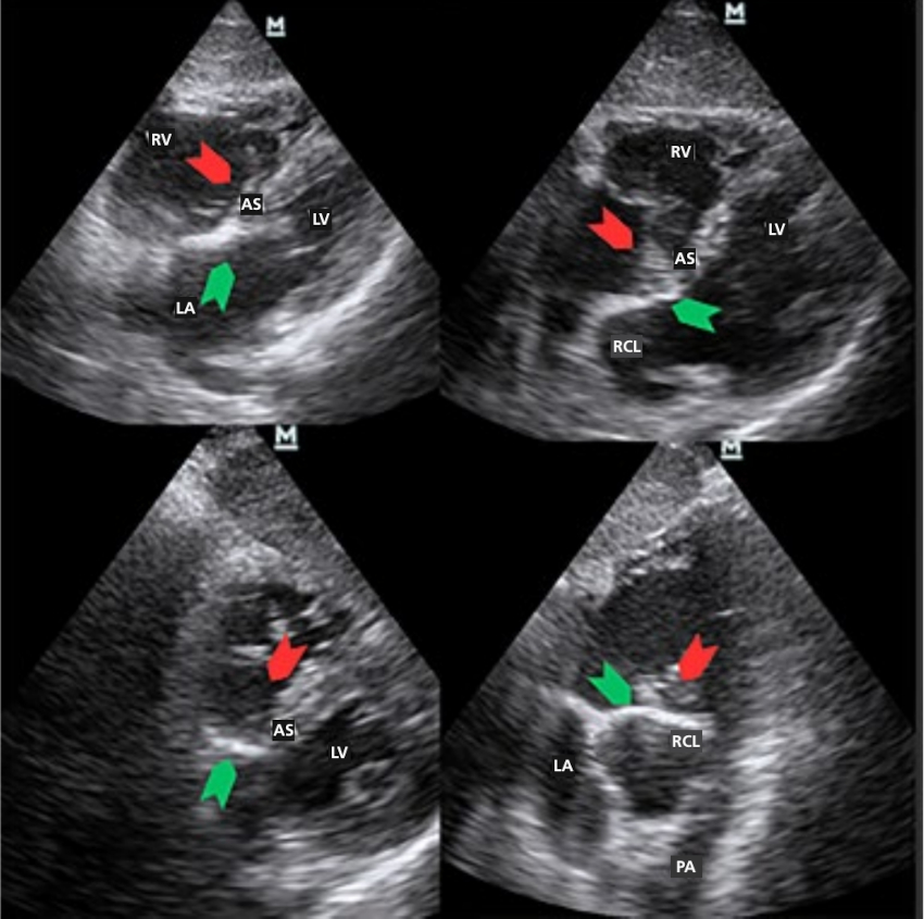
Ao: aorta; LA: left atrium; LV: left ventricle; Nc: noncoronary leaflet; PA: pulmonary artery; RCL: right coronary leaflet; RV: right ventricle. Green arrow: ascending segment (SA) of the apical loop entering the fulcrum. Red arrow: tricuspid septal leaflet. Authors’ own images.
DISCUSSION
Anatomical structure of the heart based on the continuous helical myocardium
According to Francisco Torrent Guasp (7), the helical myocardium folds unto itself to form the ventricular chambers. The myocardium assumes a helical arrangement, forming the two ventricular chambers.
In the CF are inserted muscle fibers originating from the AS of the apical loop and the DS of the basal loop, aortic root tissue, accessory tissue of the TSL, and filaments from the Aschoff-Tawara AV node. (8) In the mammalian heart, there are fibrous structures known as fibrous trigones which consist of dense connective tissue and surround the atrioventricular openings.
There are two trigones. The left trigone (LT) is located between the mitral orifice and the aorta. The right trigone (RT), a central fibrous structure, is the most prominent and is located between the tricuspid orifice (right), the aorta (posterior), and the pulmonarytricuspid cord (anterior). The trigones connect with the coronary filum, fibrous structures that surround the valve rings. The LT connects with the left coronary filum, and the RT with the right coronary filum.
Surrounding these trigones and coronary filum is connective tissue that was described by Lower as the “fibrous rings of the heart.” (9)
Cardiopulmonary and cardioaortic continuity is marked by the musculofibrous cone, which exhibits thickening at the ends of each semilunar valve. (10) Adjacent to the RT, in an anteroinferior position, lies the CF, a structure with osseous, chondroid, or tendinous histology depending on the species analyzed. (2)
The CF is the electromechanical unit of the heart where the torque produced by the contraction of both bands interacts to produce ventricular torsion and detorsion. (11,12) In heart failure and other conditions such as amyloidosis, detorsion is among the first mechanisms to be affected. (13, 14)
In hypertensive patients, ventricular suction is prolonged at the expense of an extension of the protodiastolic contraction phase of the left ventricle compared with healthy individuals. (15)
The fiber arrangement determines shape and function. This structural analysis can be demonstrated through automated tractography reconstructions of diffusion tensor magnetic resonance imaging data.
There are three twists that occur in the continuous myocardium. This arrangement, the sequential activation of the helical myocardial segments, and the anisotropic properties of their fibers determine that the electrical impulse, as it passes between these segments, produces a helical motion with opposite forces, leading to myocardial torsiondetorsion and creating the mechanical conditions necessary for mitral valve opening by suction and ventricular filling. (18,19)
Restoring both systolic and diastolic ventricular synchrony (restoration of ventricular suction) through resynchronization could be a valuable option for recovering cardiac efficiency. (20)
Acoustic impedance of the trigones, the fulcrum, and the helical myocardium
Visualization of the trigones is possible due to the high density of collagen and other proteins that make up this matrix, which appear as a bright area.
The ultrasound reflective surface is the plane separating two media with different acoustic impedances. This property is related to the density of the medium through which the ultrasound wave propagates. When the ultrasound wave strikes a surface with higher acoustic impedance than the medium through which it propagates, an echo is reflected with an intensity directly proportional to the difference in density between the media forming the reflective interface. In turn, the intensity of the sound penetrating or propagating through the medium is inversely proportional to that difference in density.
When the ultrasound strikes the trigones, coronary filum, the CF, and the muscle tissue spatially associated with the trigones, reflected echoes are produced that make up the final echocardiographic image. The trigones, coronary filum and CF produce a very intense and bright reflected echo due to the reflective interface located between the aforementioned structures.
The CF and the trigones cannot be differentiated by twodimensional echocardiography because, in humans, the difference in acoustic impedance between the structures is negligible. However, it is possible to identify the fulcrum through its anatomotopographic relationships due to its constant and unique relationship with nearby structures: the insertion base of the TSL, the RCL and nCL, and the distal end of the AS.
Limitations
We must acknowledge, on the one hand, the classic limitations of echocardiography: a) the spatial resolution of the method, which limits observation; b) acoustic impedance is similar between the trigones and the fulcrum; c) ultrasound probe settings (depth, gain, etc.). And on the other hand, those inherent to the location of the structures and their visualization: some of the echocardiographic views that best locate this complex of structures are unconventional views and axes.
The use of highfrequency transducers, other echocardiographic techniques, and the operator’s experience and skill can be crucial for obtaining highquality images and overcoming the limitations of this method.
CONCLUSION
The dissection technique described to reach the cardiac fulcrum is applicable in bovine and human hearts. The echocardiographic projections used to visualize the fibrous skeleton, CF, and the ends of the continuous helical myocardium are useful for understanding the anatomofunctional unit where ventricular torsion and detorsion occur. It is possible to identify the fulcrum through its anatomotopographic relationships due to its association with nearby structures.
The views that best identify the CF are modified 3-chamber, and apical 4-chamber views. The intermediate apical 2-chamber view (between 4-chamber and pure 2-chamber views) allows for longitudinal imaging of the fulcrum. Apical views generally allow for observation of the ascending segment entering the RT and the CF.